10 Segment LED Bar Graph Display
You may have seen these sweet looking LED bar graphs on armor like Boba Fett’s chest piece (those ones are all red). They make them in a few colors and in a rainbow of sorts, those are the ones I like. They can be easily integrated into armor and objects to add a little something extra.
Here I will help you out with how to wire them and give you some code. The wiring is up to you, and yes it requires a bit of soldering. If you do not know how to solder I would honestly push you to get some supplies and give it a whirl. Once you’ve got soldering down you can create so many things.
What does it do?
This project will make the LED bar graph light up a single bar and pulse it back and forth like a Cylon, or Kit from Knight Rider. A flip of the switch changes the mode to make the bar graph light up and blink randomly.
What you will need
- (1) 10 Segment LED display
- (10) 220 Ohm resistors
- Wire
- Solder and soldering iron
- (1) microprocessor of your choosing
- (1) small switch
- Computer with Arduino-IDE installed
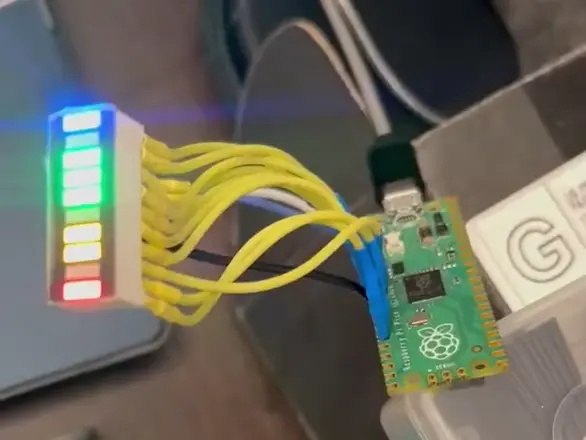
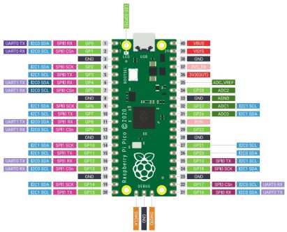
You will need a (1) 10 segment display, (1) switch small enough for your use case, (10) 220Ohm resistors (one per pin), some solder and a microprocessor board to drive it all. In the clip above I am using a Raspberry Pi Pico, and the code below is written for the RPi Pico, but you can change the pins used to accommodate other microprocessors. It is just what I had on hand. You can use almost any chip that is Arduio-IDE compatible and has enough pins to use. ESP32C3, Arduino Pro Micro, and many other ESP/Arduino boards should work just fine.
Here’s a list and links of what you will need (affiliate links):
More 10 segment colors available at Adafruit.com. Yellow, blue, green, amber, yellow-green.
The LED
The 10 segment display has 20 pins. 10 on the top, one pin per LED bar, and a negative pin (the entire bottom row) per each bar segment. Give voltage to the pins and the segment will light up for you. Feed it 3-5v DC with a 220 ohm resistor inline (per pin). Your microprocessor pins will give the bar graph the juice it needs, you do not need to wire them to power/V+. The board you choose will give out 3-5v DC to the gpio pins attached to the LED.
Wiring
You need to solder one 220 ohm resistor to each LED pin. If you are using a Pico like I did then that’s pins 2-11. The switch wires to pin 1 and ground.
The bottom row is all negative pins, ground. You can wire all of the negative pins together and attach that to one ground pin on your microprocessor board. The pins with the 220 ohm resistors wire to pins on the microprocessor. One pin per wire/pin of the 10 segment display. Once you have all 10 of the LED segments wired up and the grounds wired up we can move on to the coding part.
The Arduino IDE
I will not go over the Arduino IDE, or how to set it up for boards and libraries. There are a lot of great resources out there already for learning how to setup ESP and Pico boards with Arduino.
The Code
Fire up the Arduino-IDE and paste the following into a new sketch.
This code was written for a Raspberry Pi Pico, adjust the pins for use with a different microprocessor.
There are two sections of editable code:
This section is where you can change the pins used for the LED display and the switch.
|
1 2 3 4 |
// —– Configurable Variables —– const int switchPin = 1; // Toggle switch on pin 1 (other side connected to GND) const int ledPins[] = {2, 3, 4, 5, 6, 7, 8, 9, 10, 11}; // LED segments connected to pins 2-11 const int numLeds = sizeof(ledPins) / sizeof(ledPins[0]); |
This section is where you can adjust the speed of the pulse, and the blinking.
|
1 2 3 |
// Timing variables (in milliseconds) int pulseDelay = 100; // Delay between steps in pulse mode int blinkDelay = 500; // Delay between random blink updates |
The Full code below:
|
1 2 3 4 5 6 7 8 9 10 11 12 13 14 15 16 17 18 19 20 21 22 23 24 25 26 27 28 29 30 31 32 33 34 35 36 37 38 39 40 41 42 43 44 45 46 47 48 49 50 51 52 53 54 55 56 57 58 59 60 61 62 63 64 65 66 67 68 69 70 71 72 73 74 75 76 77 78 79 80 81 82 83 84 85 86 87 |
/* 10 Segment LED Display Revision 1.0 Author: Justin Haury Website: https://gritandbeskar.com/10-segment-display/ Description: This sketch drives a 10-segment LED bar graph connected to a Raspberry Pi Pico (using the Arduino core). – In Pulse Mode: The LEDs light up one at a time from one end to the other, then reverse. – In Random Blink Mode: Each LED randomly turns on or off slowly. The mode is selected via a toggle switch connected to pin 1 (with the other terminal connected to ground). When the switch is open (reads HIGH due to the internal pull-up), pulse mode is active. When the switch is closed (reads LOW), random blink mode is active. Configurable Variables: – LED pins are defined in the ledPins array (using pins 2 to 11). – The mode switch is connected to switchPin (pin 1). – pulseDelay and blinkDelay control the timing for the respective modes. */ // —– Configurable Variables —– const int switchPin = 1; // Toggle switch on pin 1 (other side connected to GND) const int ledPins[] = {2, 3, 4, 5, 6, 7, 8, 9, 10, 11}; // LED segments connected to pins 2-11 const int numLeds = sizeof(ledPins) / sizeof(ledPins[0]); // Timing variables (in milliseconds) int pulseDelay = 100; // Delay between steps in pulse mode int blinkDelay = 500; // Delay between random blink updates // —– Setup Function —– void setup() { // Initialize LED pins as outputs and turn them off initially. for (int i = 0; i < numLeds; i++) { pinMode(ledPins[i], OUTPUT); digitalWrite(ledPins[i], LOW); } // Initialize the mode switch pin with the internal pull-up resistor. pinMode(switchPin, INPUT_PULLUP); } // —– Main Loop —– void loop() { // If the switch is open (reads HIGH), run pulse mode. // If the switch is closed (reads LOW), run random blink mode. if (digitalRead(switchPin) == HIGH) { pulseMode(); } else { randomBlinkMode(); } } // —– Pulse Mode Function —– // Lights one LED at a time in a forward then reverse sequence. void pulseMode() { // Forward sequence: from LED 0 to LED numLeds – 1. for (int i = 0; i < numLeds; i++) { updatePulse(i); delay(pulseDelay); } // Reverse sequence: from second-to-last LED back to LED 0. for (int i = numLeds – 2; i >= 0; i—) { updatePulse(i); delay(pulseDelay); } } // Helper function for pulse mode: lights only the LED at activeIndex. void updatePulse(int activeIndex) { for (int i = 0; i < numLeds; i++) { if (i == activeIndex) { digitalWrite(ledPins[i], HIGH); } else { digitalWrite(ledPins[i], LOW); } } } // —– Random Blink Mode Function —– // Randomly sets each LED to HIGH or LOW. void randomBlinkMode() { for (int i = 0; i < numLeds; i++) { int state = random(0, 2); // Generate 0 (LOW) or 1 (HIGH) digitalWrite(ledPins[i], state); } delay(blinkDelay); } |
Verify and then upload the code and you should be good to go!